Before we start - let me categorically say that this is a bit of a tongue in cheek project. It works - you are welcome to build it if you like, but it was never intended to be anything more than a way for me to learn about using transistors and also how to use my oscilloscope. Please read the disclaimer below if you intend on using this circuit for phones!
Disclaimer: This version of the circuit (my adapted one) I am showing here will drive the cr@p out of most (if not all) headphones. In its current state you will most likely have most headphones melted to your head and be deaf for life if you are not careful with your volume control. You have been warned & I take no responsibility for any crazy things you get up to using this circuit.
Now that's over let's discuss the matter at hand:
I was reading up on some headphone amplifier designs and finally decided to try and build one. I settled on a design by Douglas Self from his book Small Signal Audio Design (ISBN 978-0-240-52177-0).
After some listening on my phones for a bit (AKG 702) I was quite impressed, but I am just not much of a phones kind of a guy. For me the phones are a reference - I don't sit and really listen to them much at all.
The next logical step was to see whether or not I could adapt the design to produce more current - you need more current to drive a lower impedance load. My speakers are 4 ohm, and your standard headphones will be between 32 and 600 ohms. In order to achieve higher current I simply added more output driver stages, and finally reduced the gain of the amp to ensure it does not clip.
The amplifier shown here will output around 2 to 2.5 Watt per channel into 4 ohm, class AB. It's not alot, but it's quite huge for a headphone amp. Frequency response is well behaved and within a very tight tolerance between 1.0 Hz (one) and 200kHz. The tolerance looks to be around 0.04V across the spectrum - based on a 2V input signal. Input impedance is 10 kOhm.
Here you can see the circuit diagram:
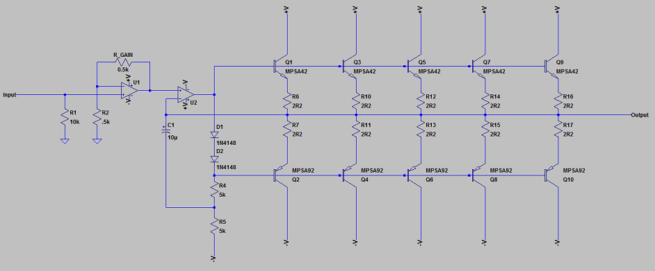
Some info on the circuit:
1. I run this on a split supply of + and - 17V. The transistors can take more, but the op-amp cannot.
2. Where you see +V in the circuit, it refers to the +17V supply rail. Where you see -V in the circuit, it refers to the -17V supply rail.
3. If you want to use this circuit to drive headphones you should make the following 2 changes:
a. The resistor marked R_GAIN can be increased to 2.5k This will give you a gain of around 5 which should be enough for most any kind of phones. For driving the 4 ohm speaker load, leave this resistor value at 0.5k for unity gain.
b. Add a resistor on the Output line after all the transistor pairs of around 30 ohm. This will give the circuit some short protection. Especially needed when plugging phones into an amplifier which is powered up. I recommend this resistor be rated for at least 5 Watt.
4. This kind of circuit does not need much current from the supply. If you have 0.3A per rail that will be more than enough. More is not a problem if you have a transformer already.
5. The 2R2 resistors which are between the transistor pairs and the output rail is used for limiting the current flowing between output devices as a result of DC offset errors.
6. This amplifier is DC coupled. This means there are no input and output capacitors. I have also not included any DC offset adjustment, so you may have a pop when switching on or off. If you don't like this then you can add a 470uF capacitor to the output rail which will block any DC from getting through.
7. The op-amp I am using here is a Texas Instruments OPA2134, but you can use a TL072 as well if you want to. The TL072 costs around 20% of the OPA2134 and performance is good enough for casual use.
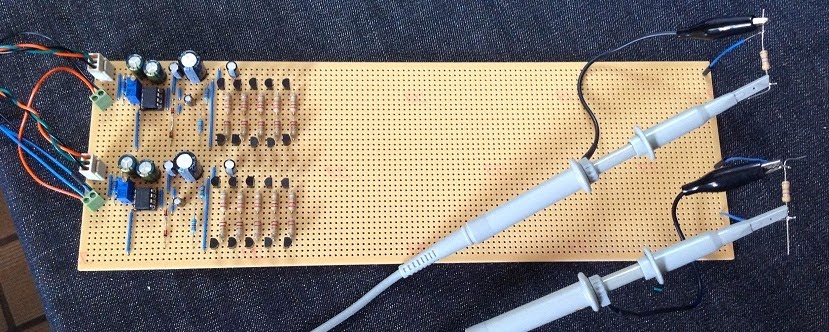
Here you can see my circuit (both channels) built on some strip-board. I have left plenty of space for adding more output devices if needed.
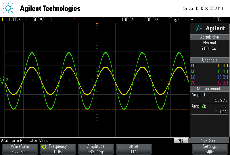
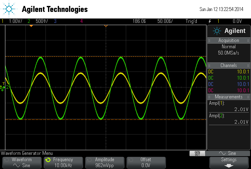
Here are some oscilloscope measurement of the board in action. The yellow trace is the input signal (generated by the scope), and the green trace is the output of the amplifier. The scale of the green trace is 2x that of the yellow trace so I could see any potential issues easily. Ignoring the scale, the input and output signal is exactly the same level because I set the gain to 1 for this version.
Measurement at 1.0 Hz (yes, that's ONE Hz):
Measurement at 10 kHz:
Measurement at 100kHz:
Measurement at 200kHz (just because I can):
The circuit starts misbehaving a bit at around 500kHz showing a slight phase shift, and at 1mHz it is distorting the signal in some strange way. Fortunately that is so far beyond the audio spectrum that it's of absolutely no concern.
So, I have this thing hooked up to my HE speakers at the moment and it's doing a pretty damned impressive job of driving them. The speakers are high 90s efficiency, so the 2 Watt output I get from the amp creates a resonable SPL level. More than loud enough for casual listening. It is a bit light on power if you want just a bit louder (I am after all used to over 440W per channel driving these), so I am going to get some more resistors and transistors and double or triple the output stage as soon as I have a chance.
How does it sound? Very difficult to explain it except to say that I am completely amazed and extremely pleased with this little circuit. It has a nice smooth sound with good detail. Good spatial information, and is pretty quiet on the noise-floor side of things. I can't wait to hear the more powerful version tho - I reckon if I can get this thing up to 5 Watt per channel then it will be enough :thumbs:
Please let me know your comments and share your own ideas with me regarding this - I am just a beginner and my electronics knowledge can fit on the back of a postage stamp so I am very happy to receive your words of wisdom.
Cheers,
Ian.
Disclaimer: This version of the circuit (my adapted one) I am showing here will drive the cr@p out of most (if not all) headphones. In its current state you will most likely have most headphones melted to your head and be deaf for life if you are not careful with your volume control. You have been warned & I take no responsibility for any crazy things you get up to using this circuit.
Now that's over let's discuss the matter at hand:
I was reading up on some headphone amplifier designs and finally decided to try and build one. I settled on a design by Douglas Self from his book Small Signal Audio Design (ISBN 978-0-240-52177-0).
After some listening on my phones for a bit (AKG 702) I was quite impressed, but I am just not much of a phones kind of a guy. For me the phones are a reference - I don't sit and really listen to them much at all.
The next logical step was to see whether or not I could adapt the design to produce more current - you need more current to drive a lower impedance load. My speakers are 4 ohm, and your standard headphones will be between 32 and 600 ohms. In order to achieve higher current I simply added more output driver stages, and finally reduced the gain of the amp to ensure it does not clip.
The amplifier shown here will output around 2 to 2.5 Watt per channel into 4 ohm, class AB. It's not alot, but it's quite huge for a headphone amp. Frequency response is well behaved and within a very tight tolerance between 1.0 Hz (one) and 200kHz. The tolerance looks to be around 0.04V across the spectrum - based on a 2V input signal. Input impedance is 10 kOhm.
Here you can see the circuit diagram:
Some info on the circuit:
1. I run this on a split supply of + and - 17V. The transistors can take more, but the op-amp cannot.
2. Where you see +V in the circuit, it refers to the +17V supply rail. Where you see -V in the circuit, it refers to the -17V supply rail.
3. If you want to use this circuit to drive headphones you should make the following 2 changes:
a. The resistor marked R_GAIN can be increased to 2.5k This will give you a gain of around 5 which should be enough for most any kind of phones. For driving the 4 ohm speaker load, leave this resistor value at 0.5k for unity gain.
b. Add a resistor on the Output line after all the transistor pairs of around 30 ohm. This will give the circuit some short protection. Especially needed when plugging phones into an amplifier which is powered up. I recommend this resistor be rated for at least 5 Watt.
4. This kind of circuit does not need much current from the supply. If you have 0.3A per rail that will be more than enough. More is not a problem if you have a transformer already.
5. The 2R2 resistors which are between the transistor pairs and the output rail is used for limiting the current flowing between output devices as a result of DC offset errors.
6. This amplifier is DC coupled. This means there are no input and output capacitors. I have also not included any DC offset adjustment, so you may have a pop when switching on or off. If you don't like this then you can add a 470uF capacitor to the output rail which will block any DC from getting through.
7. The op-amp I am using here is a Texas Instruments OPA2134, but you can use a TL072 as well if you want to. The TL072 costs around 20% of the OPA2134 and performance is good enough for casual use.
Here you can see my circuit (both channels) built on some strip-board. I have left plenty of space for adding more output devices if needed.
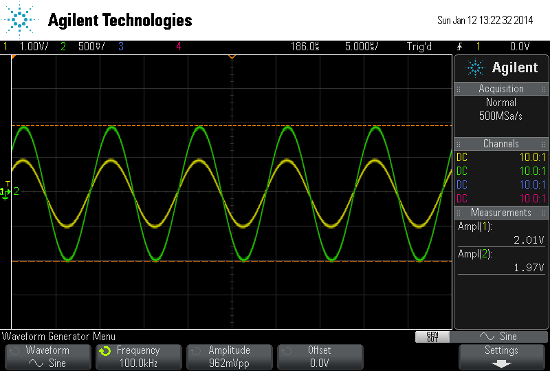
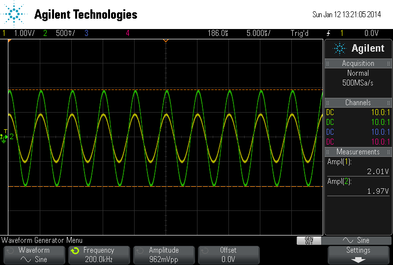
Here are some oscilloscope measurement of the board in action. The yellow trace is the input signal (generated by the scope), and the green trace is the output of the amplifier. The scale of the green trace is 2x that of the yellow trace so I could see any potential issues easily. Ignoring the scale, the input and output signal is exactly the same level because I set the gain to 1 for this version.
Measurement at 1.0 Hz (yes, that's ONE Hz):
Measurement at 10 kHz:
Measurement at 100kHz:
Measurement at 200kHz (just because I can):
The circuit starts misbehaving a bit at around 500kHz showing a slight phase shift, and at 1mHz it is distorting the signal in some strange way. Fortunately that is so far beyond the audio spectrum that it's of absolutely no concern.
So, I have this thing hooked up to my HE speakers at the moment and it's doing a pretty damned impressive job of driving them. The speakers are high 90s efficiency, so the 2 Watt output I get from the amp creates a resonable SPL level. More than loud enough for casual listening. It is a bit light on power if you want just a bit louder (I am after all used to over 440W per channel driving these), so I am going to get some more resistors and transistors and double or triple the output stage as soon as I have a chance.
How does it sound? Very difficult to explain it except to say that I am completely amazed and extremely pleased with this little circuit. It has a nice smooth sound with good detail. Good spatial information, and is pretty quiet on the noise-floor side of things. I can't wait to hear the more powerful version tho - I reckon if I can get this thing up to 5 Watt per channel then it will be enough :thumbs:
Please let me know your comments and share your own ideas with me regarding this - I am just a beginner and my electronics knowledge can fit on the back of a postage stamp so I am very happy to receive your words of wisdom.
Cheers,
Ian.