I thought it would be a good idea to start individual build topics?
And so it begins...


Not difficult at all - easier than paint-by-numbers (very limited colour palette )
)
NB:
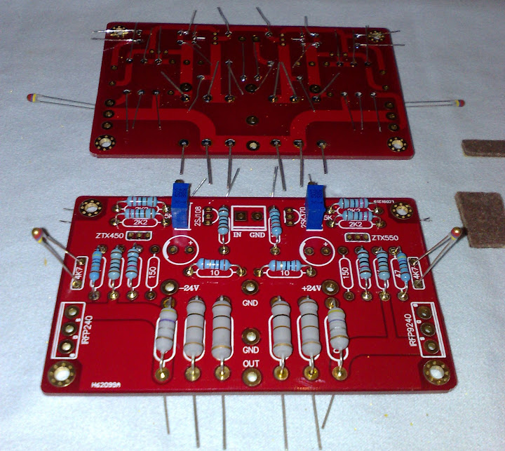
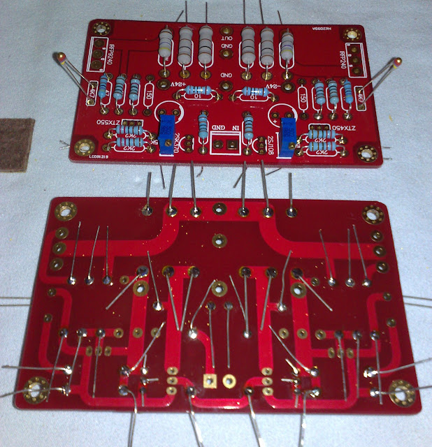
- Thermistors are in just for show since the leads are too short for permanent placement. I'll make a plan when I have a better idea about the FET placement and distance.
- Missing 150ohm resistors... Ruuuuudiii!!! ;D
;D
- 3w/2w resistors draw the heat from the soldering iron like mad - push the temperature up a bit when doing these, and let the solder flow well to the other side of the hole until it "grows" on the lead. My no-name soldering station is max 48w, I soldered everything easily with about 3/5 setting on the dial; power resistors took 3/4.
- Brown(ish) bits on the side of the PCB are humble "furniture sliding" felt pads, +- 3mm thick, cut to a rectangle where short side fits small (blue) resistor hole spacing and longer side fits the power resistors (grey) hole spacing. I place it under the resistor, bend the leads on the other side and solder. After it cools down just pull the pad out - voil?, equal spacing and nice distance from the PCB, so that you can read the values underneath and so that there is some air between the resistors and the PCB (just in case...).
- There are many (bad) resistor colour-code calculators on the Net. This one is GOOD. http://www.hobby-hour.com/electronics/resistorcalculator.php
...to be continued...
PS: All kudos to Rudi - you should see what his dining table looks like!
Kids are mixing resistors and transistors with cereal (mmmh, crunchy!), better half wears a thermistor necklace (dangerous temperatures control! )... poor puppy chews on the toroids.
And so it begins...


Not difficult at all - easier than paint-by-numbers (very limited colour palette
NB:
- Thermistors are in just for show since the leads are too short for permanent placement. I'll make a plan when I have a better idea about the FET placement and distance.
- Missing 150ohm resistors... Ruuuuudiii!!!
- 3w/2w resistors draw the heat from the soldering iron like mad - push the temperature up a bit when doing these, and let the solder flow well to the other side of the hole until it "grows" on the lead. My no-name soldering station is max 48w, I soldered everything easily with about 3/5 setting on the dial; power resistors took 3/4.
- Brown(ish) bits on the side of the PCB are humble "furniture sliding" felt pads, +- 3mm thick, cut to a rectangle where short side fits small (blue) resistor hole spacing and longer side fits the power resistors (grey) hole spacing. I place it under the resistor, bend the leads on the other side and solder. After it cools down just pull the pad out - voil?, equal spacing and nice distance from the PCB, so that you can read the values underneath and so that there is some air between the resistors and the PCB (just in case...).
- There are many (bad) resistor colour-code calculators on the Net. This one is GOOD. http://www.hobby-hour.com/electronics/resistorcalculator.php
...to be continued...
PS: All kudos to Rudi - you should see what his dining table looks like!
Kids are mixing resistors and transistors with cereal (mmmh, crunchy!), better half wears a thermistor necklace (dangerous temperatures control!


