This is one of my more ambitious DIY projects using tech and leftover parts from past commercial applications: a 500W/ch dual-mono integrated amp with internal DAC. In principle easy to do, cobble together an amp module, a potentiometer and a Chinese DAC kit and you're done. But quality will be bad. This is actually just an 'inbetween' amp since it will become redundant once my active speaker project (6 years in development and counting) is complete. The concept was conceived on boring train to Paris three years ago, and built leisurely as a low-priority project.
Chassis came from Aliexpress and CNC'd to suit. Pictures are awful, I need to work on getting a better photographing setup..
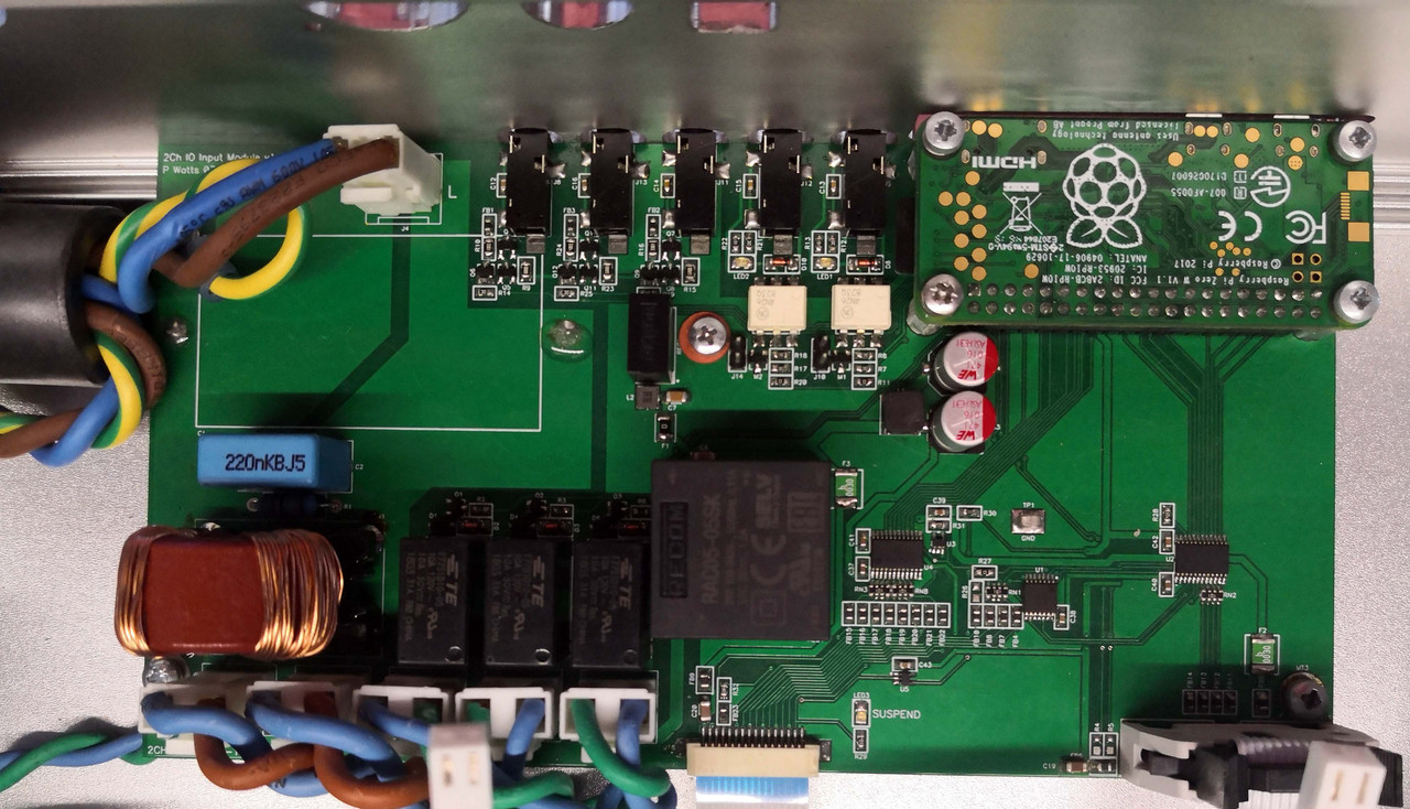
We start with the power distribution and control unit below: Mains AC enters via a fused Furutech inlet via a ferrite choke at the top left to filter the RF range. An EMI filter follows to filter out the lower frequency ranges to avoid it polluting switching noise back into the mains: all my designs are as if it were to be EMC-certified. Only the amplifiers are filtered; linear power supplies remain unfiltered. Power distribution to the amps and other power supplies are at the bottom left. Cables are thick and were a pain to work with, but sonic tests have shown that oversized cabling does make a difference. Linear power supplies are switched with three power relays.
Control is done by a Raspberry Pi Zero. This is overkill, and could have been a standard 8bit microcontroller, but it massively simplified bringup and development as I can now easily switch to different remote controls or change the behaviour via wifi. The Pi has its own dedicated isolated AC-DC power supply, and all interfaces from the Pi are heavily filtered or even isolated for the most critical tasks. The Pi does not do streaming (even though it could), it's purely for control.
Bottom centre is a flatfoil connector that goes to the front panel PCB, bottom right is the control interface to the digital audio IO board. This interface is fully isolated to 100% avoid any contamination from the Pi.
I love using 12V triggers, and the amp has 2x inputs and 3x outputs. Inputs are optically isolated, outputs are current-limited.
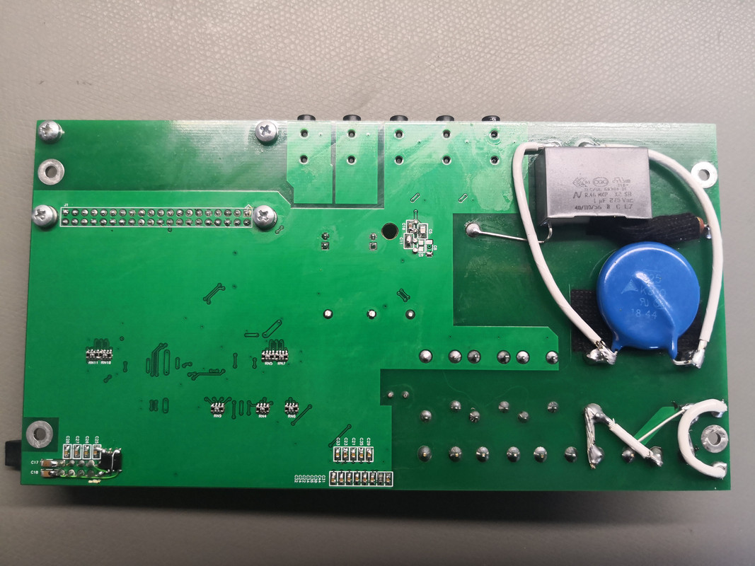
Bottom of the board is not very exciting, but I hate using PCBs for high current despite it easily being able. So I tack-solder silver-coated copper wire in parallel, and add my standard oversized MOV for protection together with an AC input snubber. An EEPROM was added as an afterthought in the bottom left to expand development options.
Next is the digital IO board. It links to the control board with the ribbon at the bottom right. Digital inputs are Toslink, coax and AES3, with very advanced input circuitry that's not just the usual termination, isolation & buffer. Analog XLR inputs are provided for HT passthrough, in that mode it's just a straigh-through power amplifier with all the other power supplies and logic switched off.
USB to I2S is provided with a heavily-modified module from Singxer: the switching regulator that powers its isolated side from the USB side got removed and is now powered from a very clean linear regulator on the mainboard. All electrolytic capacitors are replaced with oversized OS-CONs and linear regulators replaced with lower noise models. Clocks are upgraded. I kept the SPDIF output of the USB module for development but it's of course not used in the final product.
The selected input signal of the four digital sources is resampled to 96kHz 32bit using an ultra low-jitter clock.
Shielding: a 2-layer PCB can become a 3-layer with a crude but effective method of aluminium foil and copper tape joints. This assists with shielding from the AC distribution underneath.
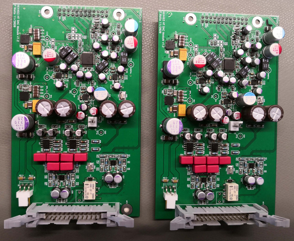
Next up are the DAC modules: based on the popular AK4493 configured as dual-mono. Bought them just before the factory burnt down, should have got more.. Three of the lowest noise regulators are used for critical reference rails, plus two more for digital. Signal path is fully differential throughout, with very low-noise opamps used. Opamps are regulated once again with ultra low-noise regulators. PCBs are 4-layer for optimal ground, power and signal integrity. A relay at the output switches the input to the amplifier between DAC line driver output and HT bypass input.
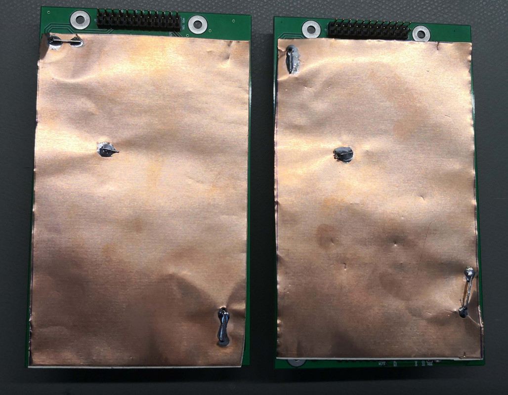
Bottom the same technique is used to add a shielding layer, this time with copper foil throughout.
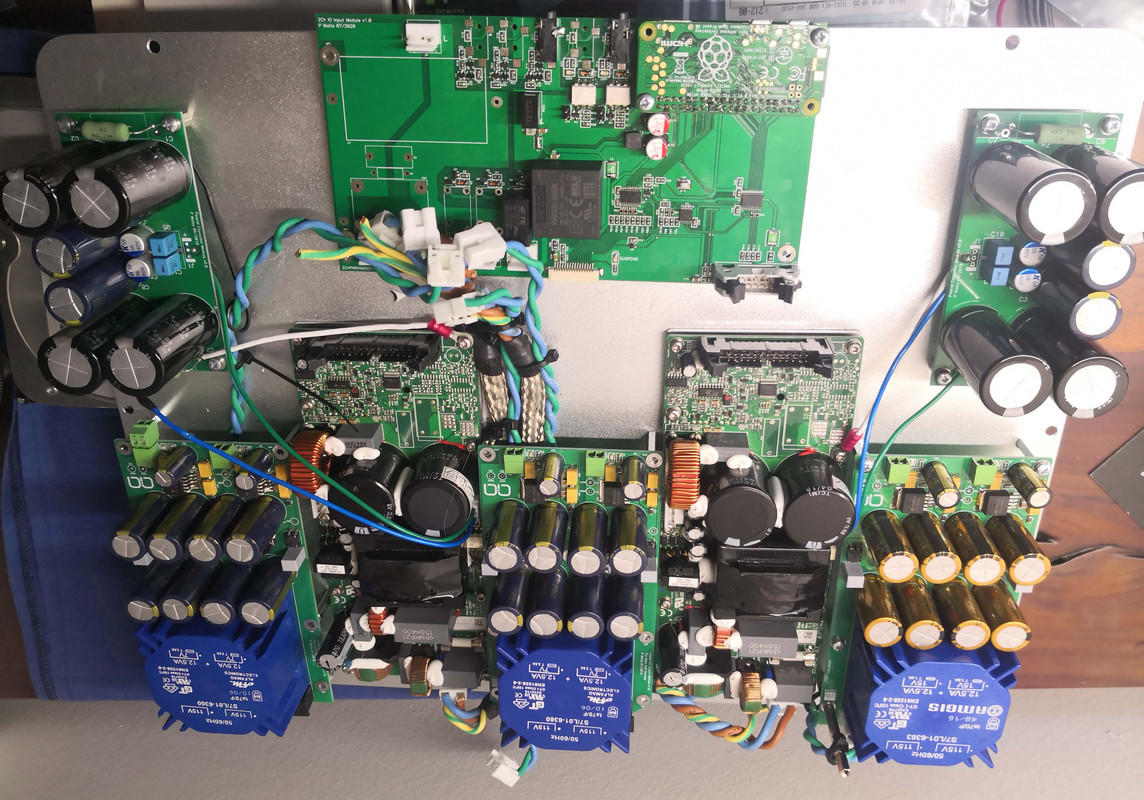
Early stages of assembly. Amplifiers are Pascal T-PRO1 monoblocks with integrated power supplies and heavy customizations. It has an augmented DC power capacitor bank with a range of electrolytic, polymer and film capacitors. Electrolytics are Nichicon Audio grade. AC power cabling are jacketed in a shielded braid.
The three additional power supplies come from a past project and are split-rail to provide highly filtered & regulated DC for analog buffers, DAC analog left, DAC analog right, clock and digital circuitry respectively.
Further progression: IO module added, front & rear panels together with Furutech binding posts and speaker cabling.
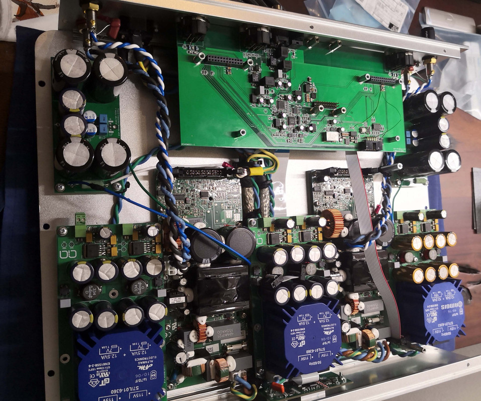
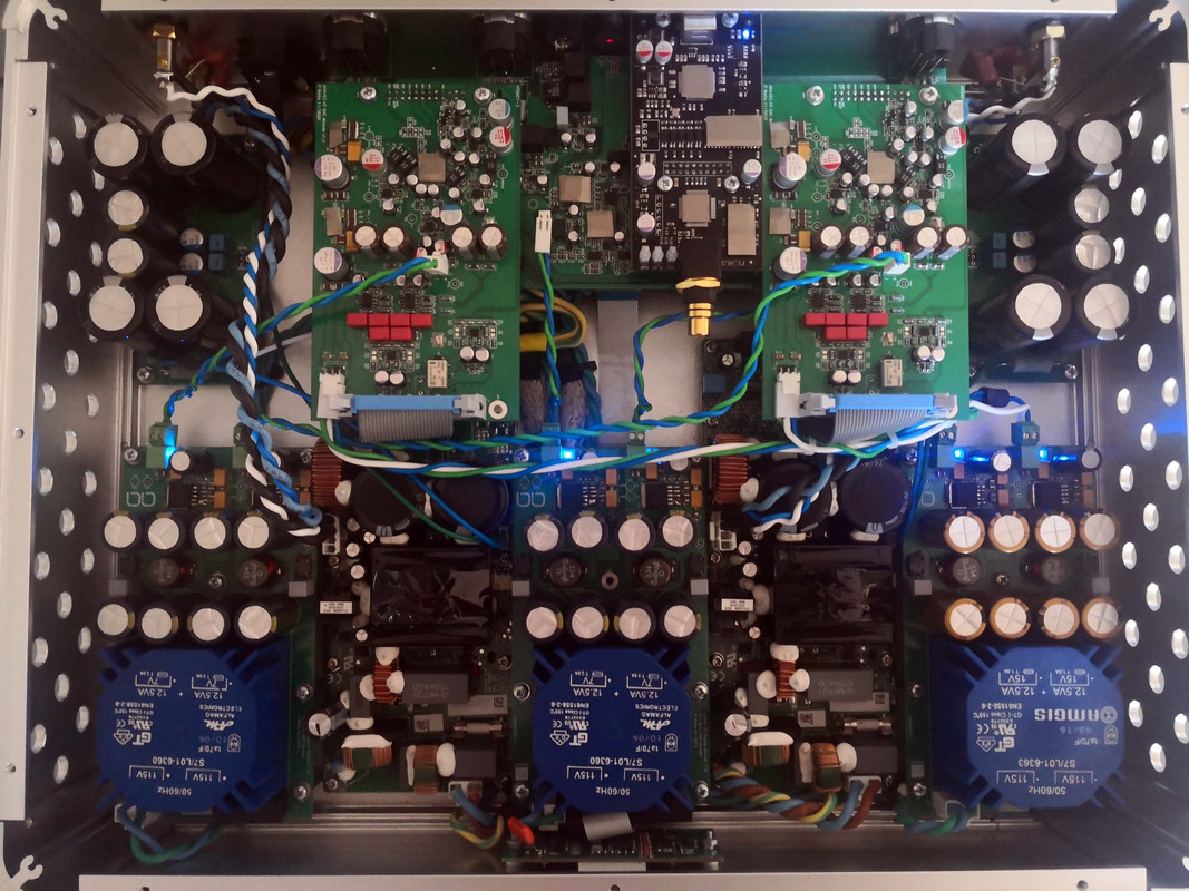
Final product prior to closing the lid: all cabling finished, definitely not pretty but optimal for best results of getting power directly where it is needed without traversing through other noisy PCB planes. Side panels are drilled for airflow, technically not needed but I believe in reducing temperature as much as possible to prolong capacitor lifespan.
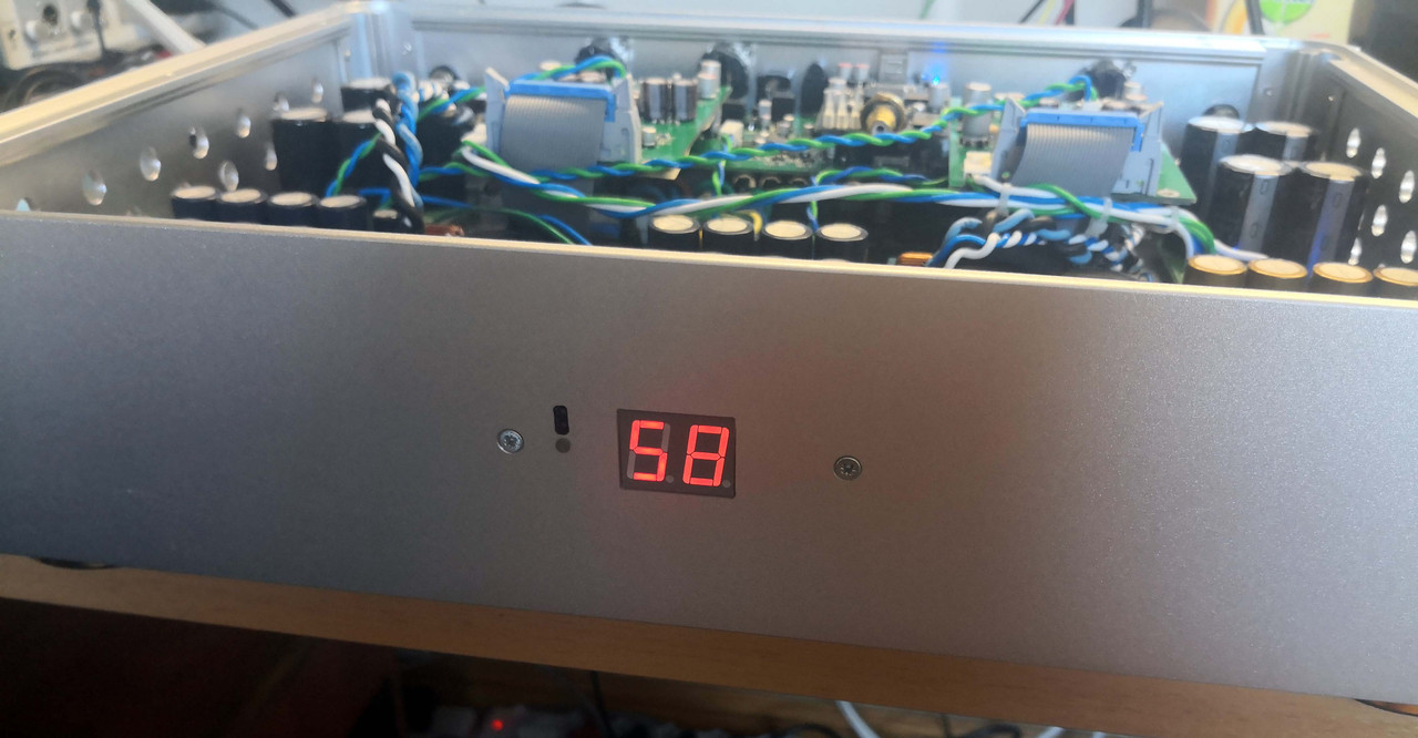
Chassis front, showing very utilitarian feedback. One red/white LED to indicate standby and HT bypass respectively, and a RGB 7segment display for volume when in DAC mode. Red as shown is for Toslink input, green for coax, blue for AES3 and purple for USB. The dots are used to show mute. IR is controlled using an Apple remote. I may still add a smoked perspex window to cover it and round it off.
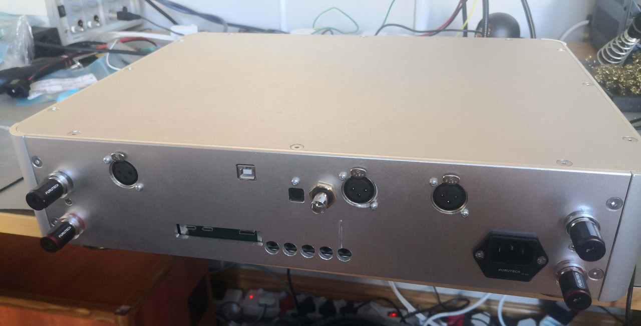
Chassis rear. The CNC shop botched it up royally, but what's done is done. Fortunately it's out of view when in use.
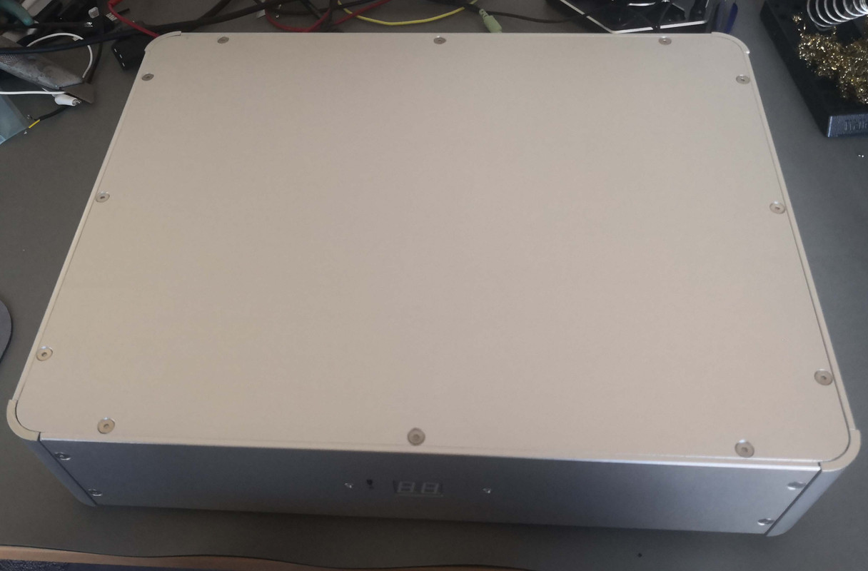
Done! Everything closed and good to go. Sound? Well it makes a good toot. Well more than that, it makes a bloody good toot. Still need to put it properly through its paces but for now I'm very pleased. Some small software changes needed and it can go in the equipment rack.
Chassis came from Aliexpress and CNC'd to suit. Pictures are awful, I need to work on getting a better photographing setup..
We start with the power distribution and control unit below: Mains AC enters via a fused Furutech inlet via a ferrite choke at the top left to filter the RF range. An EMI filter follows to filter out the lower frequency ranges to avoid it polluting switching noise back into the mains: all my designs are as if it were to be EMC-certified. Only the amplifiers are filtered; linear power supplies remain unfiltered. Power distribution to the amps and other power supplies are at the bottom left. Cables are thick and were a pain to work with, but sonic tests have shown that oversized cabling does make a difference. Linear power supplies are switched with three power relays.
Control is done by a Raspberry Pi Zero. This is overkill, and could have been a standard 8bit microcontroller, but it massively simplified bringup and development as I can now easily switch to different remote controls or change the behaviour via wifi. The Pi has its own dedicated isolated AC-DC power supply, and all interfaces from the Pi are heavily filtered or even isolated for the most critical tasks. The Pi does not do streaming (even though it could), it's purely for control.
Bottom centre is a flatfoil connector that goes to the front panel PCB, bottom right is the control interface to the digital audio IO board. This interface is fully isolated to 100% avoid any contamination from the Pi.
I love using 12V triggers, and the amp has 2x inputs and 3x outputs. Inputs are optically isolated, outputs are current-limited.

Bottom of the board is not very exciting, but I hate using PCBs for high current despite it easily being able. So I tack-solder silver-coated copper wire in parallel, and add my standard oversized MOV for protection together with an AC input snubber. An EEPROM was added as an afterthought in the bottom left to expand development options.

Next is the digital IO board. It links to the control board with the ribbon at the bottom right. Digital inputs are Toslink, coax and AES3, with very advanced input circuitry that's not just the usual termination, isolation & buffer. Analog XLR inputs are provided for HT passthrough, in that mode it's just a straigh-through power amplifier with all the other power supplies and logic switched off.
USB to I2S is provided with a heavily-modified module from Singxer: the switching regulator that powers its isolated side from the USB side got removed and is now powered from a very clean linear regulator on the mainboard. All electrolytic capacitors are replaced with oversized OS-CONs and linear regulators replaced with lower noise models. Clocks are upgraded. I kept the SPDIF output of the USB module for development but it's of course not used in the final product.
The selected input signal of the four digital sources is resampled to 96kHz 32bit using an ultra low-jitter clock.

Shielding: a 2-layer PCB can become a 3-layer with a crude but effective method of aluminium foil and copper tape joints. This assists with shielding from the AC distribution underneath.
Next up are the DAC modules: based on the popular AK4493 configured as dual-mono. Bought them just before the factory burnt down, should have got more.. Three of the lowest noise regulators are used for critical reference rails, plus two more for digital. Signal path is fully differential throughout, with very low-noise opamps used. Opamps are regulated once again with ultra low-noise regulators. PCBs are 4-layer for optimal ground, power and signal integrity. A relay at the output switches the input to the amplifier between DAC line driver output and HT bypass input.

Bottom the same technique is used to add a shielding layer, this time with copper foil throughout.

Early stages of assembly. Amplifiers are Pascal T-PRO1 monoblocks with integrated power supplies and heavy customizations. It has an augmented DC power capacitor bank with a range of electrolytic, polymer and film capacitors. Electrolytics are Nichicon Audio grade. AC power cabling are jacketed in a shielded braid.
The three additional power supplies come from a past project and are split-rail to provide highly filtered & regulated DC for analog buffers, DAC analog left, DAC analog right, clock and digital circuitry respectively.

Further progression: IO module added, front & rear panels together with Furutech binding posts and speaker cabling.

Final product prior to closing the lid: all cabling finished, definitely not pretty but optimal for best results of getting power directly where it is needed without traversing through other noisy PCB planes. Side panels are drilled for airflow, technically not needed but I believe in reducing temperature as much as possible to prolong capacitor lifespan.

Chassis front, showing very utilitarian feedback. One red/white LED to indicate standby and HT bypass respectively, and a RGB 7segment display for volume when in DAC mode. Red as shown is for Toslink input, green for coax, blue for AES3 and purple for USB. The dots are used to show mute. IR is controlled using an Apple remote. I may still add a smoked perspex window to cover it and round it off.

Chassis rear. The CNC shop botched it up royally, but what's done is done. Fortunately it's out of view when in use.

Done! Everything closed and good to go. Sound? Well it makes a good toot. Well more than that, it makes a bloody good toot. Still need to put it properly through its paces but for now I'm very pleased. Some small software changes needed and it can go in the equipment rack.


