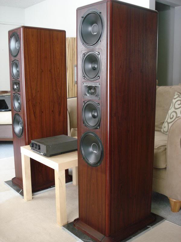
Recently acquired these.

Mine are not as pretty (unfinished boxes) but they are good supawood cabinets built to withstand nuclear war
When I opened them up I found a two way Mission 765 crossover network, wired with the two bass drivers in parallel. The two midrange units were not connected. I got the proper 767 crossovers too.

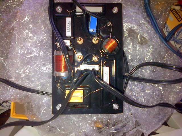
The 767 crossover came like this with wires soldered. Two leads for bass units - these are straight through because the 767 is supposed to be used with its own bass amp/equaliser, the "Low Frequency Alignment Unit" (LFAU). One lead for the HF unit - fine. But one lead for the two midrange units :thinking: I couldn't find out from my googlings whether the midrange units are wired in series or parallel. In parallel this presents a hefty load - 3.8ohm nominal. Should I try both series and parallel connections? I have a work around for the LFAU so the bass units are powered by a separate amp. A clue may be that the crossover panel states that the combined nominal impedance of MR and HF is 8ohms. All advice welcome!

Mine are not as pretty (unfinished boxes) but they are good supawood cabinets built to withstand nuclear war
When I opened them up I found a two way Mission 765 crossover network, wired with the two bass drivers in parallel. The two midrange units were not connected. I got the proper 767 crossovers too.

The 767 crossover came like this with wires soldered. Two leads for bass units - these are straight through because the 767 is supposed to be used with its own bass amp/equaliser, the "Low Frequency Alignment Unit" (LFAU). One lead for the HF unit - fine. But one lead for the two midrange units :thinking: I couldn't find out from my googlings whether the midrange units are wired in series or parallel. In parallel this presents a hefty load - 3.8ohm nominal. Should I try both series and parallel connections? I have a work around for the LFAU so the bass units are powered by a separate amp. A clue may be that the crossover panel states that the combined nominal impedance of MR and HF is 8ohms. All advice welcome!
