Time for something a bit more challenging: a proper streamer. In December I enquired and [member=60]gavinbirss[/member] pointed me to the Swiss EngineeRED products. Basically the are an OEM company supplying modules to manufacturers integrating their modules (Audiomat Maestro 3 to name one), but also market the modules and suitable baseboards to the DIY community. So I ordered a baseboard and module to play with.
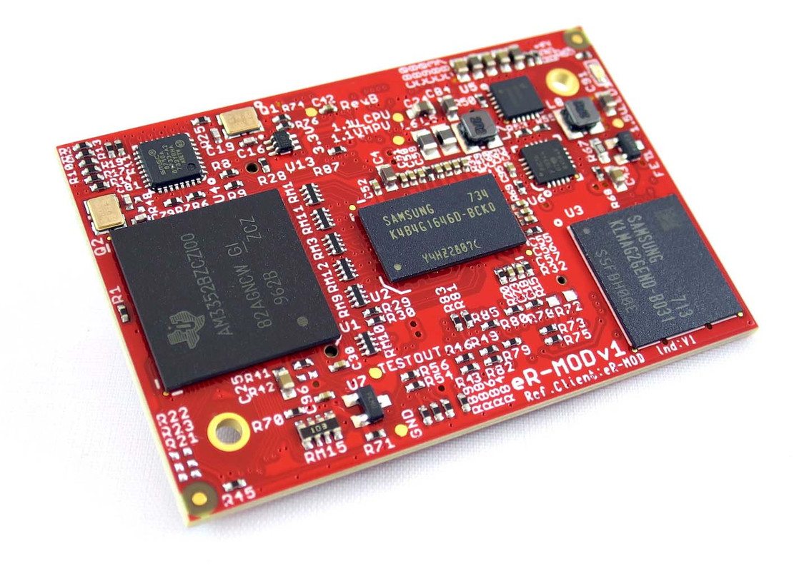
The module is tiny and based on a a Texas Instruments ARM CPU.
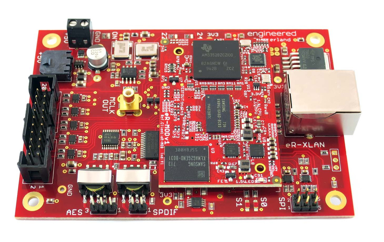
The DIY'ers all use it with the baseboard which turned out to be surprisingly good as it uses quality components and proper design:
However, it just felt wrong to copy the other DIY'ers by just plonking the evalkit with a nice power supply in a chassis, plus I wanted I2S outputs that's not on a ribbon header and I found other areas I thought could do with improvement. Of course it spiraled a bit out of control, since I wanted to experiment with concepts and had some leftover materials I could reuse.
All details below, but here are two inside shots of the final design. Pictures are not great as I just wanted to close up and begin using it Somehow it also looks a bit skew but everything is nice and straight. The DC cabling was deliberately done the way it is to keep it separated and away from picking up stray noise.
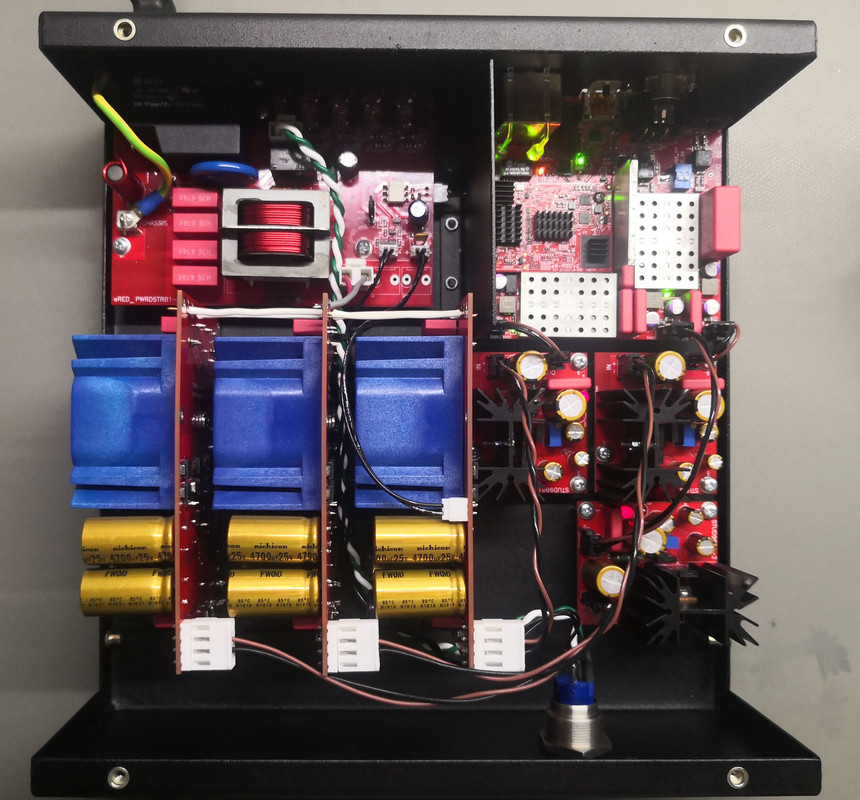
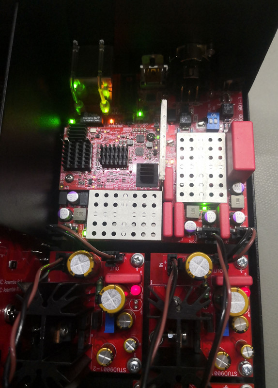
Everything except for the module was custom designed and assembled. Some highlights:
- Three separate power headers for the module, clock and S/PDIF/AES3/I2S and extensive additional filtering prior to regulation. These are in turn powered from massively overkill dedicated power supplies, given that the total power consumption is less than 2W.
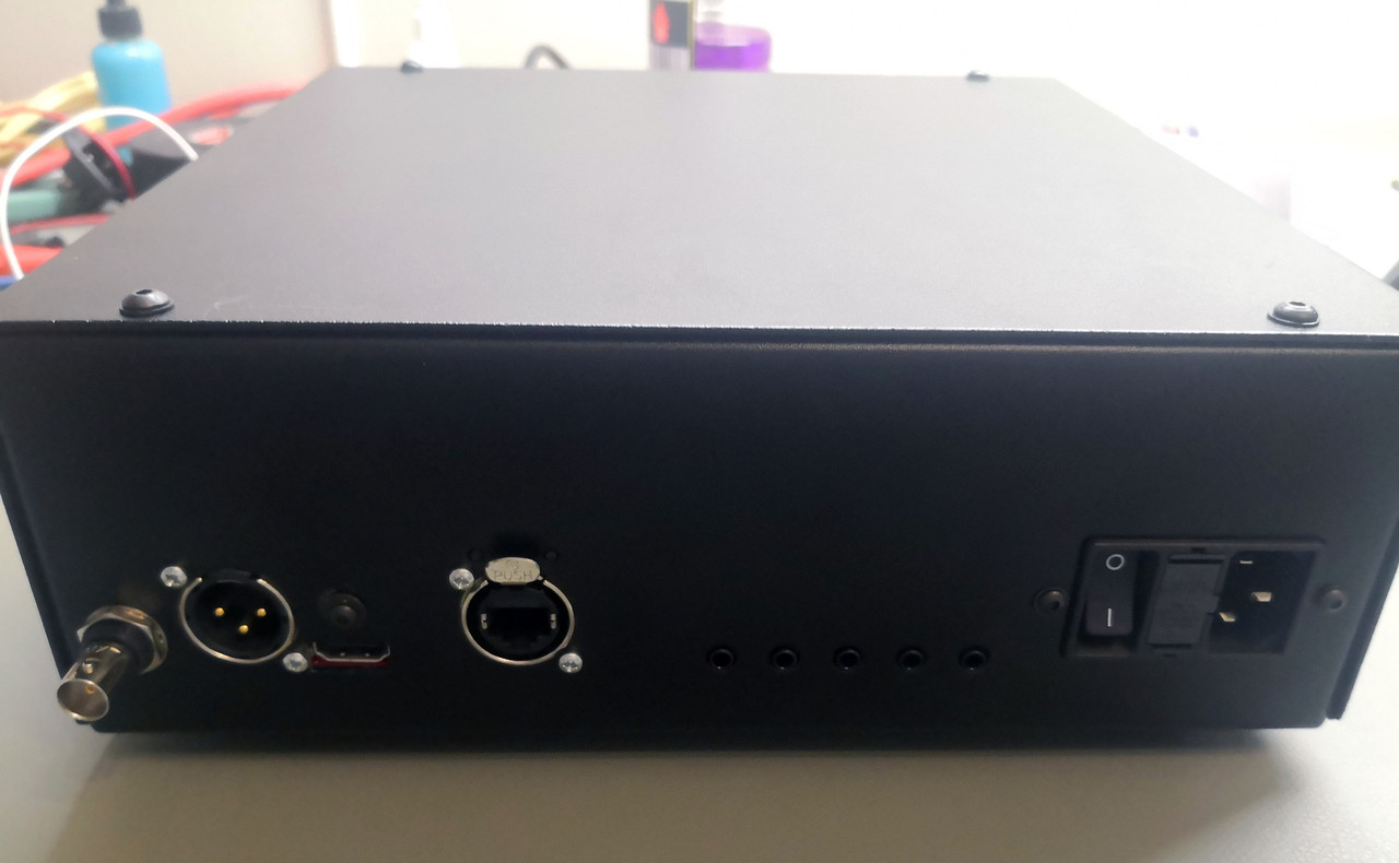
- Proper Neutrik Ethercon with separate transformers sporting less parasitic leakage and higher ESD immunity that integrated Magjacks. It costs more and takes more board space though.
- AES3 & S/PDIF on BNC, with good circuit conditioning (this is one of the biggest drawbacks of the baseboard which uses only pinstrips for these two outputs)
- I2S on HDMI output following the polarity/pinout of PS Audio. A multiplexer was used selection option of PCM or DSD.
- Very quiet regulators everywhere, specially identified for the application.
- DIP switches to deactivate the S/PDIF or I2S power supply respectively since in reality only one output will be used. Less current means less ripple and noise, and less crosstalk from unused radiating interfaces.
- Shield cages for the clock circuit and S/PDIF sections respectively, plus a grid to solder a 'wall' between the MOD and the rest.
- Lots of passive filtering including OSCON electrolytics, Wima MKP10 film and the most resilient ceramic dielectrics.
- Buffered header for SPI and UART if needed
- Heat sinks from an RPi kit was added to the chips in the module as they get a bit hot. The heat itself is not the issue, but heat deltas cause change in signal timing, so limiting that helps with consistent performance.
- Extreme care with PCB layout to ensure the shortest and purest signal paths of critical signals without crosstalk or integrity loss.
For cost purposes I had to keep the board below 100x100mm which proved quite a challenge since I had to use 4 PCB layers and the costs sharply jumps when exceeding those dimensions. Same goes for not using gold plating, which does not really offer any advantage except ease of solderability and bare board shelf life. Since noise isolation and shielding was a big part of the design criteria, there is deliberately no front panel/LCD or other settings to minimize any noise that may occur.
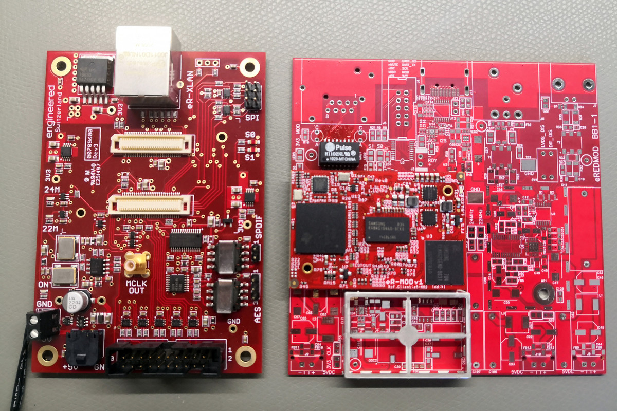
Below is a picture comparing the original baseboard to mine in early stage of assembly. I do not usually like red solder mask but thought it befitting to suit the module colour.
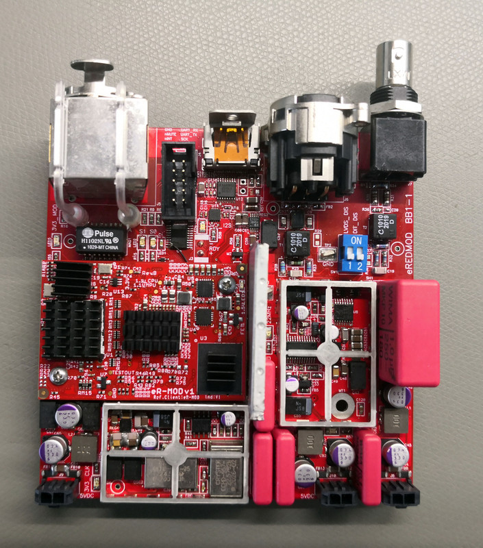
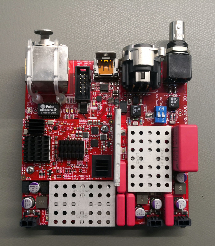
This is the top side of the final module, with and without the cage covers:
The power supply is a two-stage affair of vertically mounted unregulated supplies, then a separate regulator for each to in turn power the clocks, digital output, and module respectively.
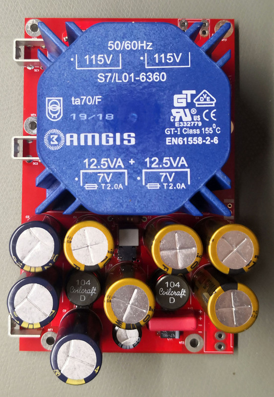
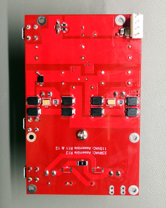
The top and bottom of the DC power module are shown below: nothing special, just a 25VA transformer with damper, soft recovery Schottky diodes, common mode filtering, staggered RC and LC filters and a combination of film, electrolytic, tantalum and ceramic capacitors. Total capacitance per PSU is just under 40,000uF.
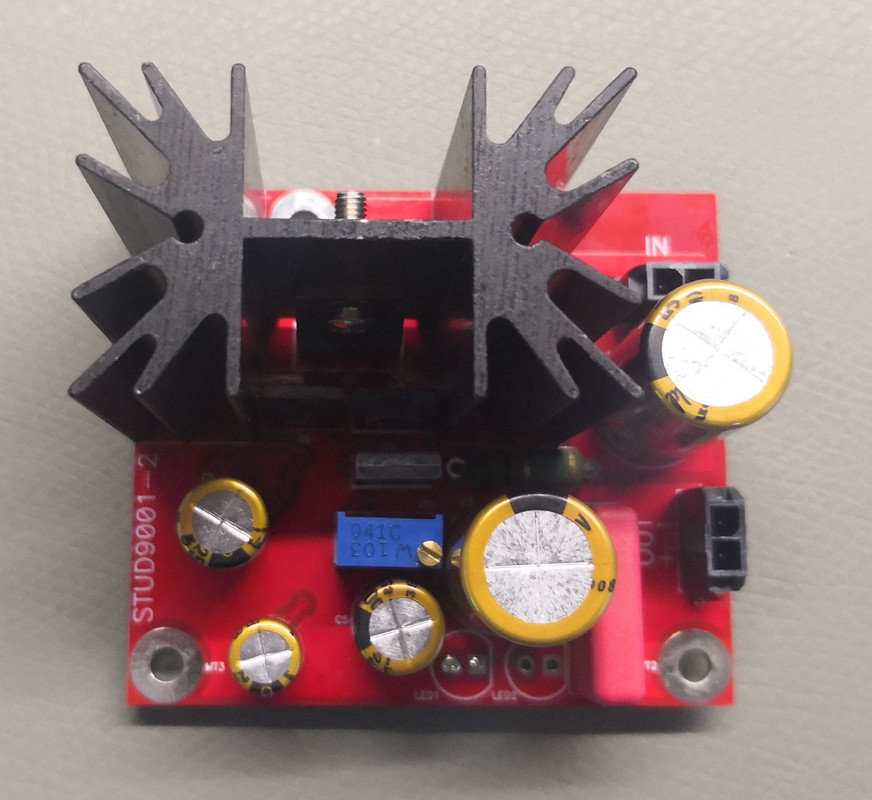
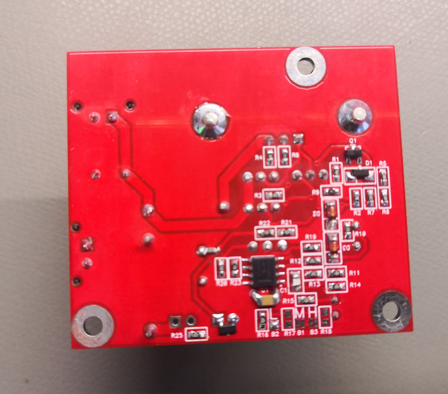
Below are the regulation modules, they are derived from the Studer 900 concept which I changed a bit and made a very compact and suitable circuit setup with many SMT devices. The overall result is one of the best regulators I have ever encountered with extreme precision and stability.
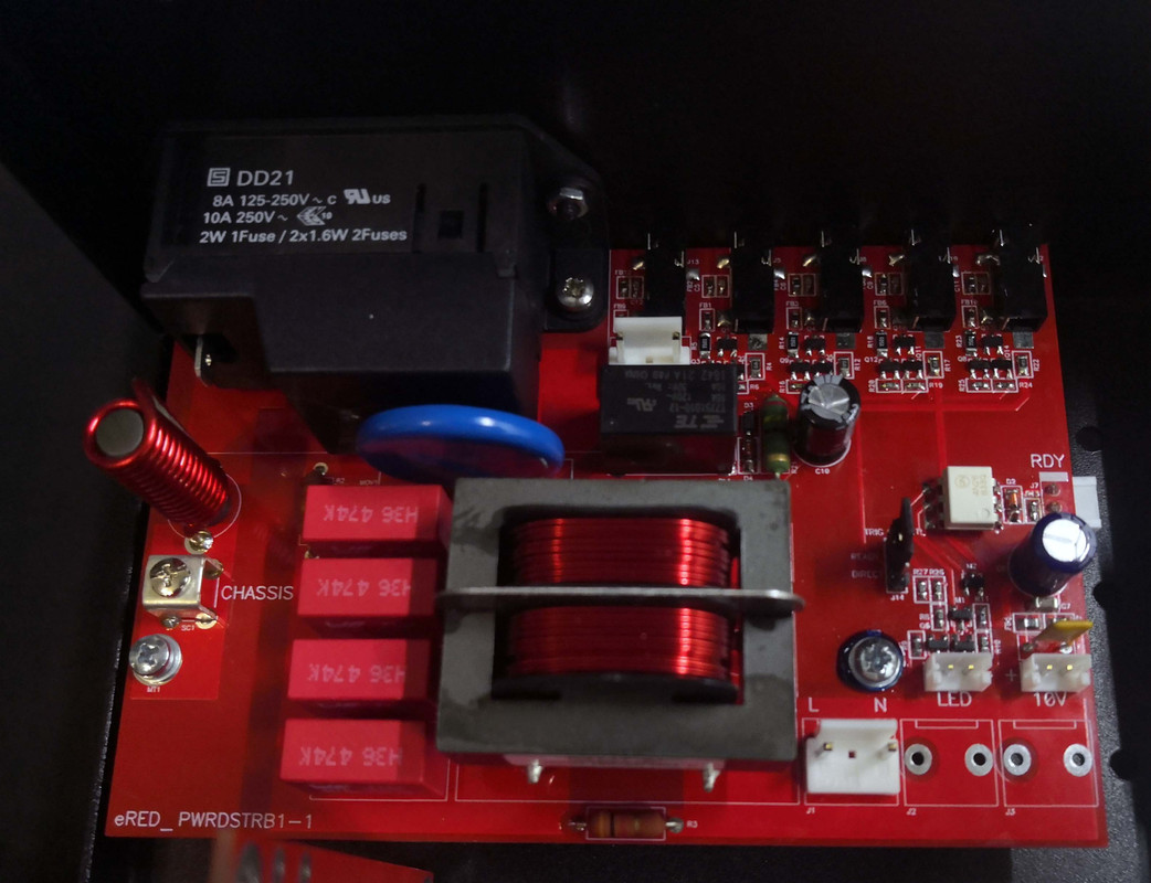
Finally, the power input module which I made as general-purpose design for other projects too. It has an excellent AC power input filter, largely based on the Fo-Felix AC filter concept, but with some modifications. It also has a 12V DC trigger input and four current limited buffered trigger outputs to drive an entire network of other devices such as DACs, preamps and amps. The trigger outputs can be configured to activate with the input or after the module has completed booting and connected to its DHCP server.
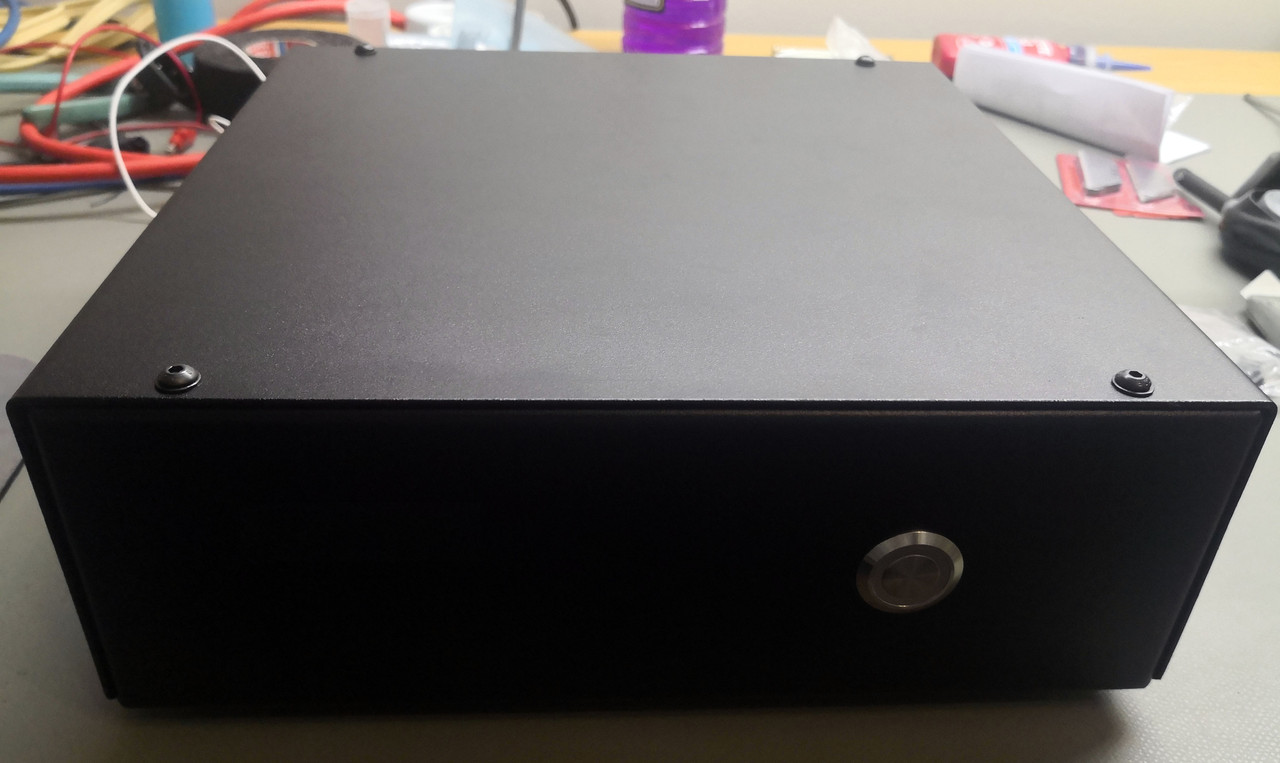
There was nothing revolutionary or fancy about the chassis since it was custom made and will be in an equipment rack anyway. I preferred this over hacking apart a commercial DIY enclosure since I can optimize the size and layout exactly to my requirements. Once all my related projects are done I'll have nice matching engraved aluminium faceplates machined that will just bolt at the front. Chassis is powdercoated bent steel. Power supplies, input, module and regulators have been optimally placed to be space-saving while still allowing decent separation of critical parts. I've also added a steel "wall" between the module and the power inlet to help with some shielding.
On the front is just a simple power switch with a two-color LED ring. It lights up red while the module is booting (or whatever else is wrong), then turns green when ready to stream. All non-control wiring is silver-coated OFC with Teflon insulation: there is no signal wiring at all since everything is contained on the PCB.
Overall I am extremely happy with the result. Can't comment too much on the performance as it doesn't add functionality beyond what the stock mainboard does, but I think mine sounds better and the output waveforms are definitely cleaner. Power supply noise is also less. I haven't tested the I2S output yet because I don't have an I2S DAC with me yet, but the intention is for it to be used with my upcoming 9 channel DSP/DAC active speaker project, but with AKM's factory fire it will have to wait a bit while I finish other projects. Overall the intention though is to use it with my upcoming custom Ethernet switch and PCIe network interface card.
The only issue I have/had is that Roon is not supported: initially I was miffed but then discovered it is not a product limitation but rather because Roon certifies a product, not an underlying core design - commercial deployments of these modules happily support Roon. So in principle I could submit this to Roonlabs for certification but that would just be daft, so I'm going to settle on Audioirvana.
The module is tiny and based on a a Texas Instruments ARM CPU.

The DIY'ers all use it with the baseboard which turned out to be surprisingly good as it uses quality components and proper design:

However, it just felt wrong to copy the other DIY'ers by just plonking the evalkit with a nice power supply in a chassis, plus I wanted I2S outputs that's not on a ribbon header and I found other areas I thought could do with improvement. Of course it spiraled a bit out of control, since I wanted to experiment with concepts and had some leftover materials I could reuse.
All details below, but here are two inside shots of the final design. Pictures are not great as I just wanted to close up and begin using it


Everything except for the module was custom designed and assembled. Some highlights:
- Three separate power headers for the module, clock and S/PDIF/AES3/I2S and extensive additional filtering prior to regulation. These are in turn powered from massively overkill dedicated power supplies, given that the total power consumption is less than 2W.
- Proper Neutrik Ethercon with separate transformers sporting less parasitic leakage and higher ESD immunity that integrated Magjacks. It costs more and takes more board space though.
- AES3 & S/PDIF on BNC, with good circuit conditioning (this is one of the biggest drawbacks of the baseboard which uses only pinstrips for these two outputs)
- I2S on HDMI output following the polarity/pinout of PS Audio. A multiplexer was used selection option of PCM or DSD.
- Very quiet regulators everywhere, specially identified for the application.
- DIP switches to deactivate the S/PDIF or I2S power supply respectively since in reality only one output will be used. Less current means less ripple and noise, and less crosstalk from unused radiating interfaces.
- Shield cages for the clock circuit and S/PDIF sections respectively, plus a grid to solder a 'wall' between the MOD and the rest.
- Lots of passive filtering including OSCON electrolytics, Wima MKP10 film and the most resilient ceramic dielectrics.
- Buffered header for SPI and UART if needed
- Heat sinks from an RPi kit was added to the chips in the module as they get a bit hot. The heat itself is not the issue, but heat deltas cause change in signal timing, so limiting that helps with consistent performance.
- Extreme care with PCB layout to ensure the shortest and purest signal paths of critical signals without crosstalk or integrity loss.
For cost purposes I had to keep the board below 100x100mm which proved quite a challenge since I had to use 4 PCB layers and the costs sharply jumps when exceeding those dimensions. Same goes for not using gold plating, which does not really offer any advantage except ease of solderability and bare board shelf life. Since noise isolation and shielding was a big part of the design criteria, there is deliberately no front panel/LCD or other settings to minimize any noise that may occur.
Below is a picture comparing the original baseboard to mine in early stage of assembly. I do not usually like red solder mask but thought it befitting to suit the module colour.

This is the top side of the final module, with and without the cage covers:


The power supply is a two-stage affair of vertically mounted unregulated supplies, then a separate regulator for each to in turn power the clocks, digital output, and module respectively.
The top and bottom of the DC power module are shown below: nothing special, just a 25VA transformer with damper, soft recovery Schottky diodes, common mode filtering, staggered RC and LC filters and a combination of film, electrolytic, tantalum and ceramic capacitors. Total capacitance per PSU is just under 40,000uF.


Below are the regulation modules, they are derived from the Studer 900 concept which I changed a bit and made a very compact and suitable circuit setup with many SMT devices. The overall result is one of the best regulators I have ever encountered with extreme precision and stability.


Finally, the power input module which I made as general-purpose design for other projects too. It has an excellent AC power input filter, largely based on the Fo-Felix AC filter concept, but with some modifications. It also has a 12V DC trigger input and four current limited buffered trigger outputs to drive an entire network of other devices such as DACs, preamps and amps. The trigger outputs can be configured to activate with the input or after the module has completed booting and connected to its DHCP server.

There was nothing revolutionary or fancy about the chassis since it was custom made and will be in an equipment rack anyway. I preferred this over hacking apart a commercial DIY enclosure since I can optimize the size and layout exactly to my requirements. Once all my related projects are done I'll have nice matching engraved aluminium faceplates machined that will just bolt at the front. Chassis is powdercoated bent steel. Power supplies, input, module and regulators have been optimally placed to be space-saving while still allowing decent separation of critical parts. I've also added a steel "wall" between the module and the power inlet to help with some shielding.
On the front is just a simple power switch with a two-color LED ring. It lights up red while the module is booting (or whatever else is wrong), then turns green when ready to stream. All non-control wiring is silver-coated OFC with Teflon insulation: there is no signal wiring at all since everything is contained on the PCB.


Overall I am extremely happy with the result. Can't comment too much on the performance as it doesn't add functionality beyond what the stock mainboard does, but I think mine sounds better and the output waveforms are definitely cleaner. Power supply noise is also less. I haven't tested the I2S output yet because I don't have an I2S DAC with me yet, but the intention is for it to be used with my upcoming 9 channel DSP/DAC active speaker project, but with AKM's factory fire it will have to wait a bit while I finish other projects. Overall the intention though is to use it with my upcoming custom Ethernet switch and PCIe network interface card.
The only issue I have/had is that Roon is not supported: initially I was miffed but then discovered it is not a product limitation but rather because Roon certifies a product, not an underlying core design - commercial deployments of these modules happily support Roon. So in principle I could submit this to Roonlabs for certification but that would just be daft, so I'm going to settle on Audioirvana.
