I needed a break from the PCB layouts I am doing for the relay based attenuator, so after getting my mind around the what and how of the design, I started making proper hard-core volume knob.
Life started out as a billet of 6068 T6 aluminium about 88mm diameter, and 80mm long.
Actually, this specific piece of aluminium nearly killed me in my early days of learning how to work the lathe. It came out of the chuck at 950 rpm and flew past my head and hit into the brick wall behind me. I have been keeping this specific piece for a special project seeing as we have such a colorful history together :whistler:
Things still need a final buffing, but the machining is just about done...
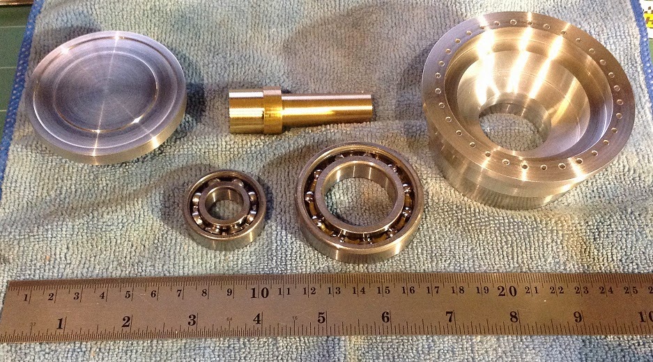
Here you can see all the parts. Left to right, Top to bottom:
actual volume knob; shaft; block; SKF deep groove ball bearing 35mm OD, 15mm ID; SKF deep groove ball bearing 55mm OD, 30mm ID
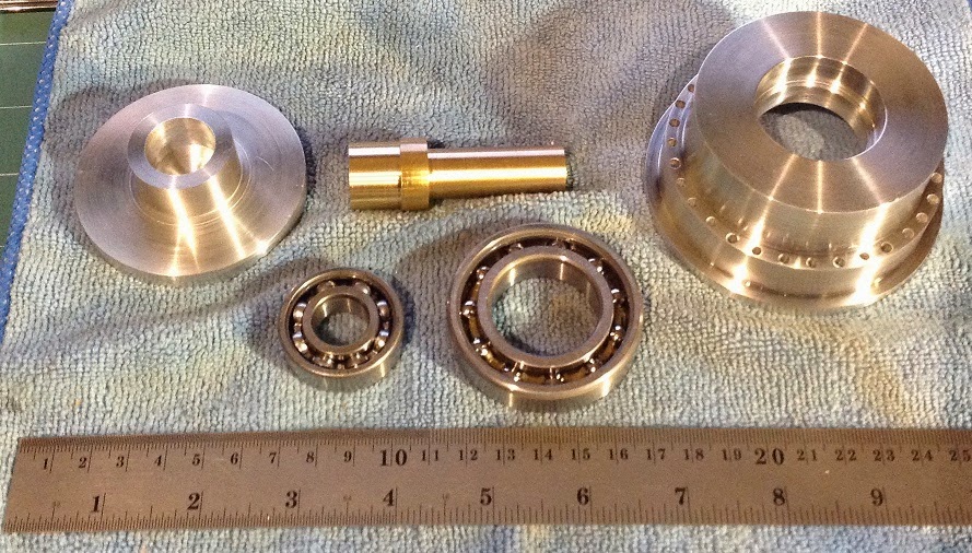
And this is what the back of the volume knob and block look like:
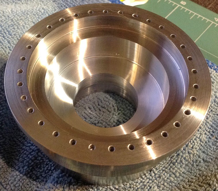
Front of the block:
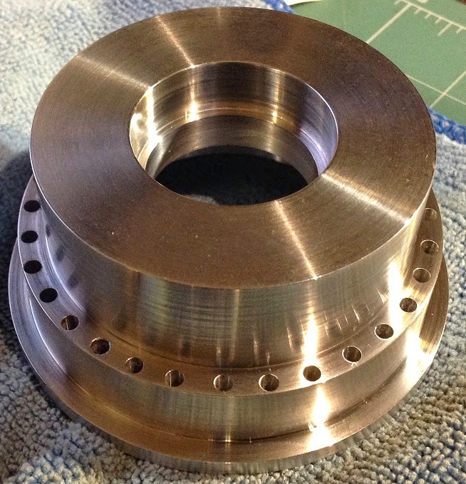
Back of the block:
This is the smaller of the two bearings sitting in the block. It press fits to be flush.
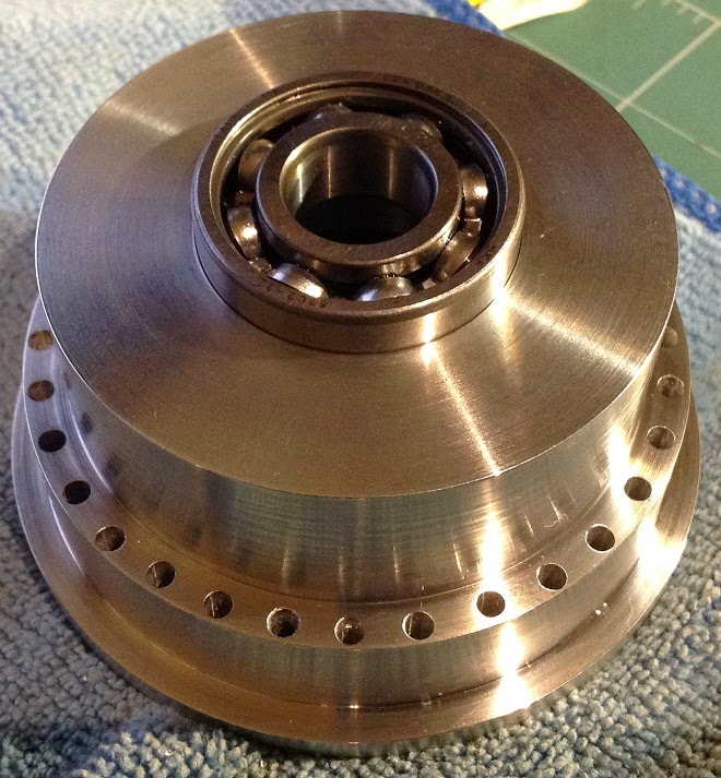
This is the larger of the two bearings sitting in the block. It press fits.
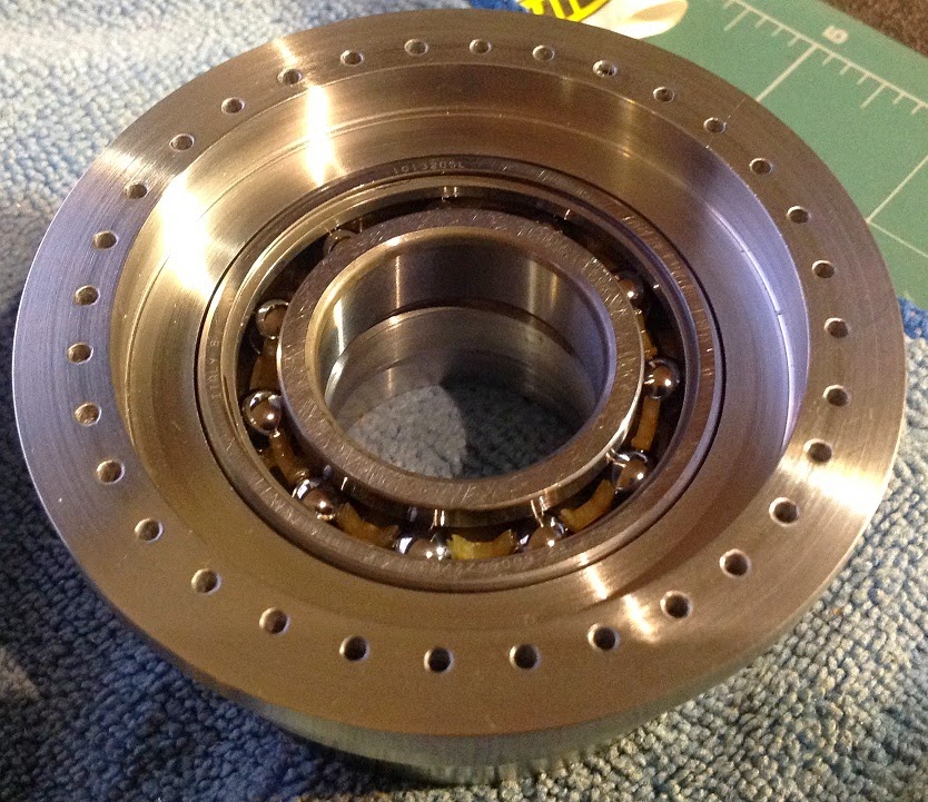
The volume knob with the shaft (also press fit), and the large bearing taken out of the block to show how it couples to the assembly:
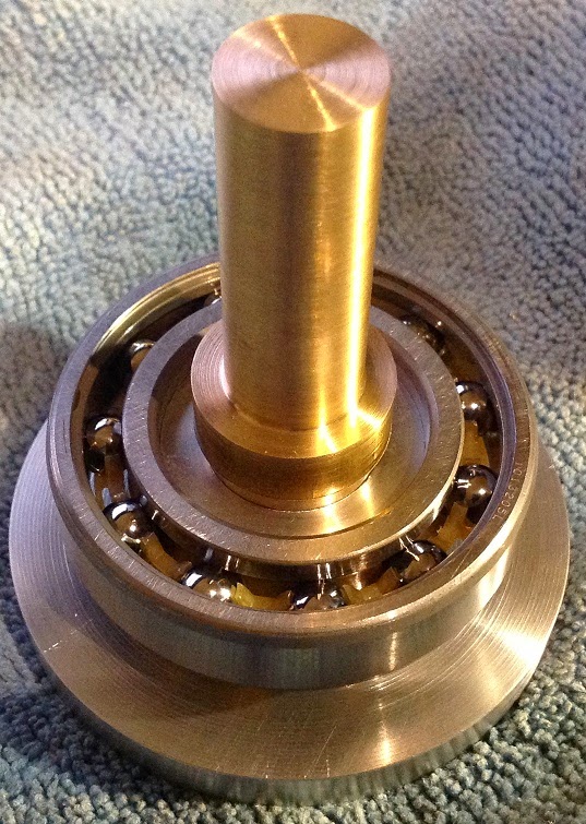
"dry assembly" front view:
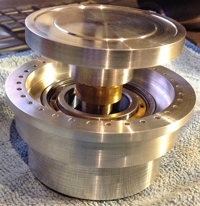
"dry assembly" rear view:
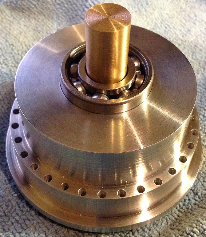
This is by far the most accurate machining job I have ever done. I was making cuts down to 0.005mm resolution on some of the bits - especially the bearing seats. You want the bearing to be held in place by the seat, so it must be press fit without needing excessive force. Some light tapping with a mallet and a piece of wood should be enough to seat it.
Those small holes around the perimeter of the block will each house a LED. The front has been drilled out to 2mm diameter, and the backs have been opened up to 3mm diameter. There are 32 of these holes, meaning I will have 32 LEDs mounted. I will switch only 1 on at a time, and that will be the volume level indicator.
So, next I need to machine the brass shaft down a bit where it comes out of the assembly. Probably down from the current 15mm to about 6 or 8mm. This will allow me to connect it to a gear or toothed pulley which will allow me to drive a rotary encoder or volume pot or whatever.
After that I will give everything a good cleaning followed by a polish. Then it's assembly time!
I am a bit worried about the assembly. Everything will fit perfectly - that I am confident of. What worries me is the idea that I may need to disassemble. After all the press fits this thing isn't coming apart very easily...
Anyway - cheers for now!
Ian.
Life started out as a billet of 6068 T6 aluminium about 88mm diameter, and 80mm long.
Actually, this specific piece of aluminium nearly killed me in my early days of learning how to work the lathe. It came out of the chuck at 950 rpm and flew past my head and hit into the brick wall behind me. I have been keeping this specific piece for a special project seeing as we have such a colorful history together :whistler:
Things still need a final buffing, but the machining is just about done...
Here you can see all the parts. Left to right, Top to bottom:
actual volume knob; shaft; block; SKF deep groove ball bearing 35mm OD, 15mm ID; SKF deep groove ball bearing 55mm OD, 30mm ID

And this is what the back of the volume knob and block look like:

Front of the block:

Back of the block:

This is the smaller of the two bearings sitting in the block. It press fits to be flush.

This is the larger of the two bearings sitting in the block. It press fits.

The volume knob with the shaft (also press fit), and the large bearing taken out of the block to show how it couples to the assembly:

"dry assembly" front view:

"dry assembly" rear view:

This is by far the most accurate machining job I have ever done. I was making cuts down to 0.005mm resolution on some of the bits - especially the bearing seats. You want the bearing to be held in place by the seat, so it must be press fit without needing excessive force. Some light tapping with a mallet and a piece of wood should be enough to seat it.
Those small holes around the perimeter of the block will each house a LED. The front has been drilled out to 2mm diameter, and the backs have been opened up to 3mm diameter. There are 32 of these holes, meaning I will have 32 LEDs mounted. I will switch only 1 on at a time, and that will be the volume level indicator.
So, next I need to machine the brass shaft down a bit where it comes out of the assembly. Probably down from the current 15mm to about 6 or 8mm. This will allow me to connect it to a gear or toothed pulley which will allow me to drive a rotary encoder or volume pot or whatever.
After that I will give everything a good cleaning followed by a polish. Then it's assembly time!
I am a bit worried about the assembly. Everything will fit perfectly - that I am confident of. What worries me is the idea that I may need to disassemble. After all the press fits this thing isn't coming apart very easily...
Anyway - cheers for now!
Ian.
